BMSOne (4S) $42 [wp_DISABLEDcart:BMSOne-4S:price:42:shipping:4:end]
BMSOne (5S) $42 [wp_DISABLEDcart:BMSOne-5S:price:42:shipping:4:end]

BMSOne w/XT60 $47 [wp_DISABLEDcart:BMSOne-6S:price:42:shipping:4:end]
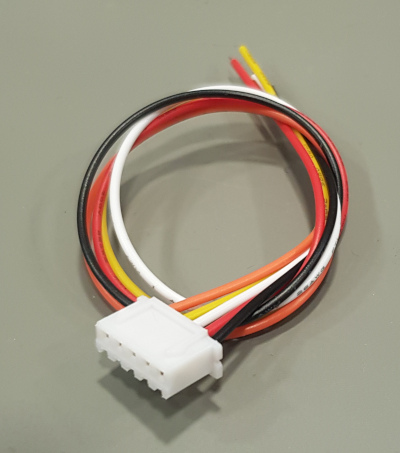
20cm balancing cable JST-HX $1 [wp_DISABLEDcart:Balancing cable:price:1:shipping:0:end]
[show_wp_shoDISABLEDpping_cart]
THIS PRODUCT IS ONLY AVAILABLE THRU https://jonbrotherton.fws.store/product/bmsone-v2-plug-and-play
Description:
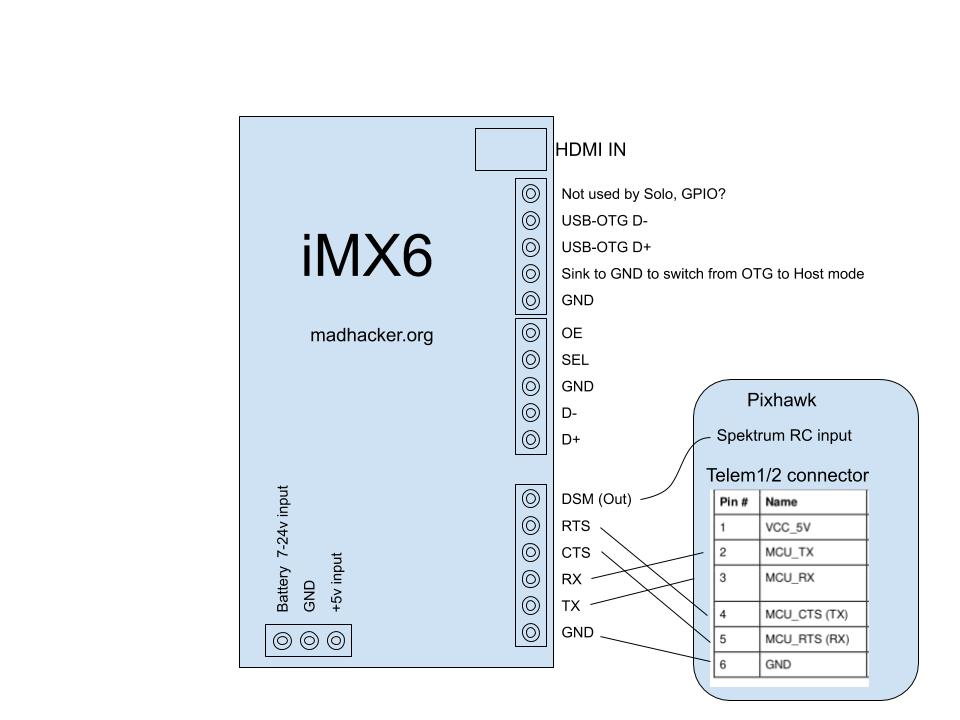
This device is not limited to 3DR Solo, but build to work with any 2S-6S battery and ArduPilot.
Provides a realistic state of charge and individual cell voltages.
3DR Solo can use any Li-xx battery in 4S to 5S configuration. (The Solo gimbal is not compatible with 6S)
The PCB is less than 50x40x9mm (the balancing connector is the highest component) The weight is only 7.9g
The device in 4S, 5S, and 6S configurations is exactly the same, fully populated with all components. The only difference is the balancing connector.
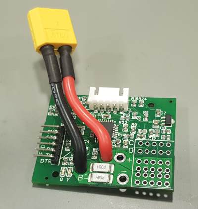
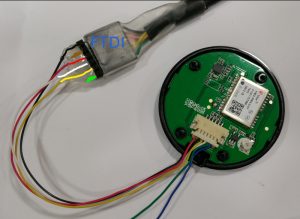
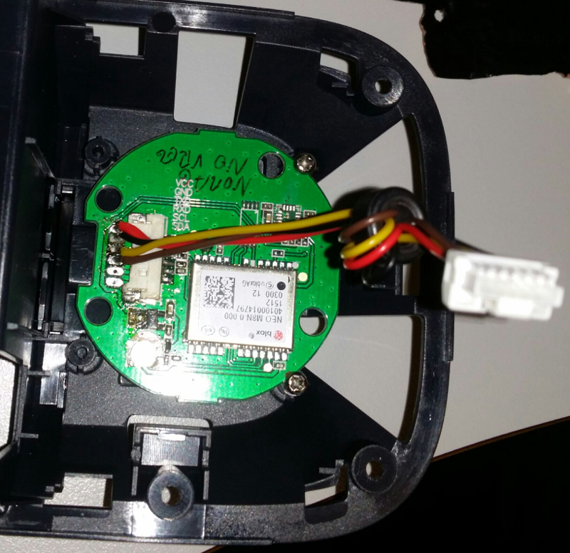
Super-Simple, Plug & Play version:
If you dislike configuration, finding a suitable battery, etc.. please see the super-user-friendly version made by some nice people at: https://jonbrotherton.fws.store/product/bmsone-v2-plug-and-play
Basically: It gives you a simple plug-and-play solution, none of the setup/configure/install/mount stuff.
4-6S Support with older ArduPilot:
The older ArduPilot and Solo support 4S batteries.
If you connect BMSOne with 5 or 6 cells to an older ArduPilot it will automatically spoof a 4S battery consisting of four of your lowest-voltage cells – while providing the full 5/6S voltage of your pack.
This way, it is perfectly backward-compatible, and safety is maintained by always reporting the lowest cells.
4-6S Support with newer ArduPilot:
Newer ArduPilot can use the 4-6s capability of BMSOne.
You will see all cells.
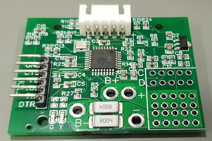
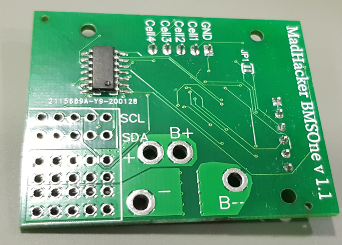
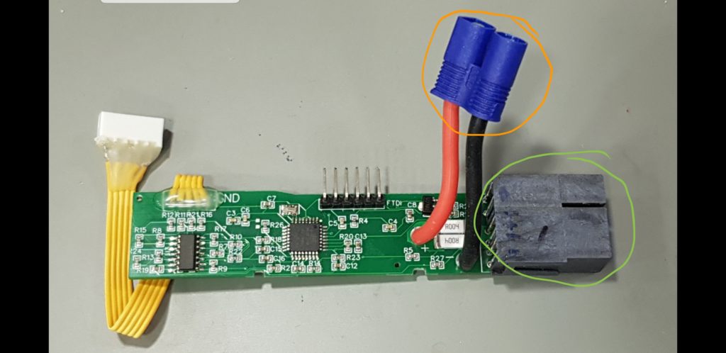
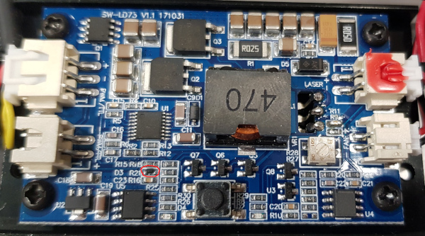
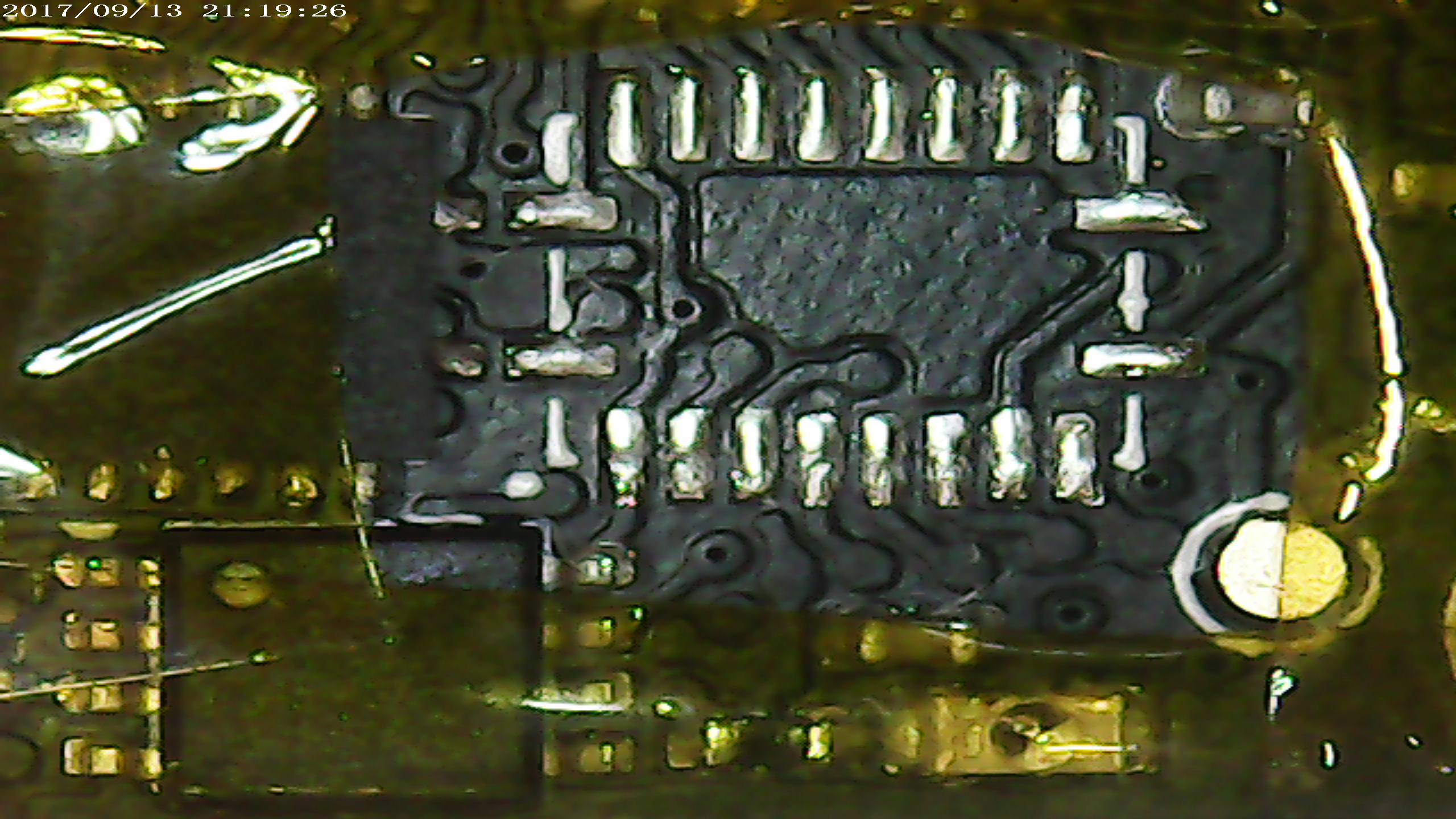
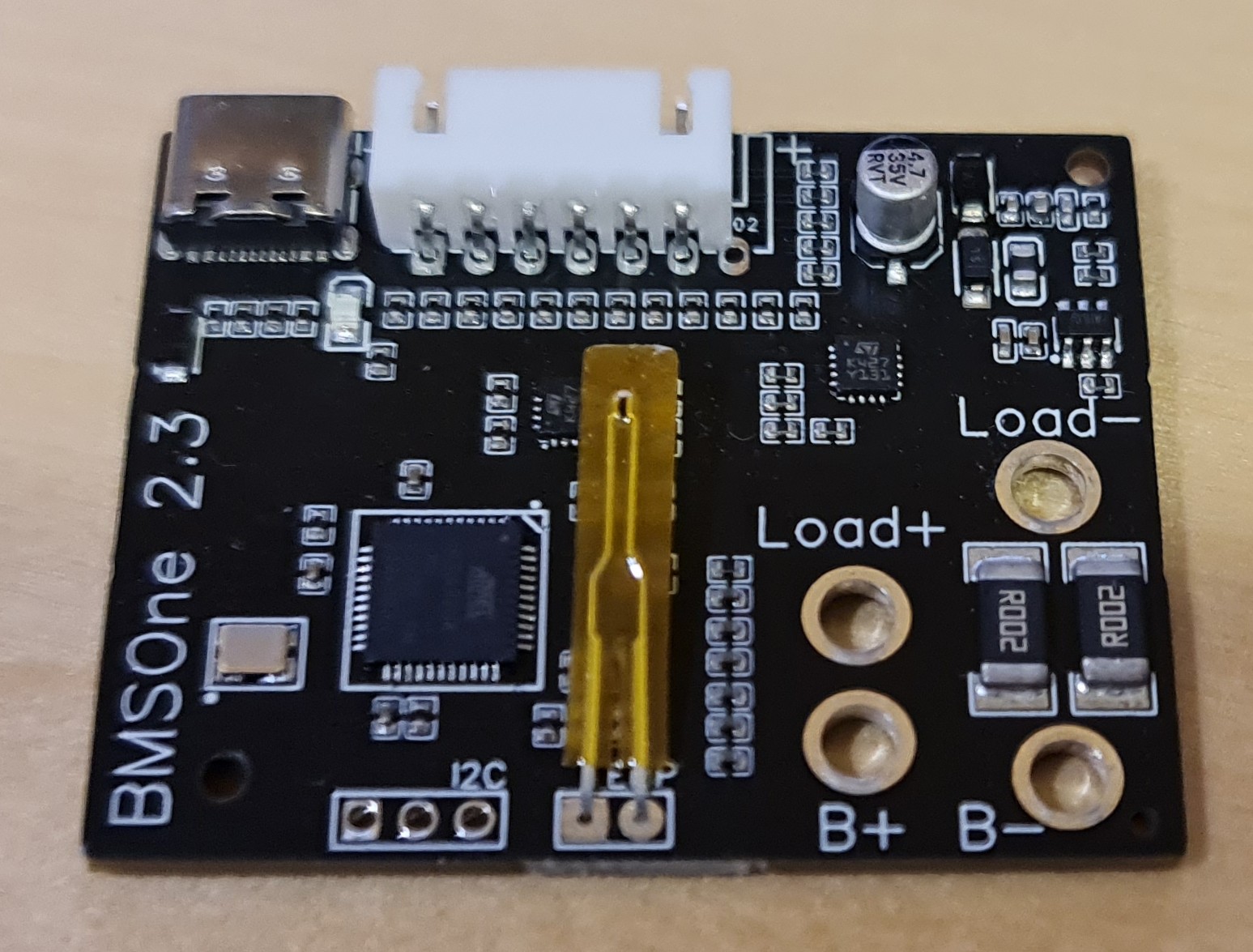
This is the BMSOne:


Old hardware 2.3 to the left, and 3.1 (Current version) to the right.
Configuration:
Configuration, like firmware updates, is done using the USB-C port.
Configuration commands in BOLD:
When you connect to it at 115200kbps, (8N1) and power it up, you will see: BMSOne v2.0
Set the capacity of the battery in mAh using the command:
SM10000
it will respond:Set capacity: 10000
Now, you have defined a 10Ah full capacity.
The device can provide remaining capacity information based on one of the methods:
S0 //remaining capacity is estimated based on voltage.
S1 //remaining capacity is reported based on mAh consumed (assumes you start with a fully charged battery of defined capacity on boot)
S! // No thermistor, fake 22.5°C temperature
SH //100K Thermistor
SW //write configuration to flash – until you do this, all your changes/calibration are temporary and can be reverted by rebooting the device.
SN //Use new Protocol (up to 6S)
SO //Use old protocol, 4S – you can still use 5S/6S batteries, but only 4 lowest cells will be listed, and BMS will emulate a 4S battery.
SR //read config from flash (it happens on every boot)
SS //Prints voltage and percent tables, capacity values, thermistor and protocol settings.
SD //Show internal data, rints ADC readings, cell multipliers, pack voltage, temperature, current, etc.
S~ // erase EEPROM (reset the configuration to firmware defaults/factory reset)
ST // invert current multiplier
On hardware >2.x:
SWx / SRx //Write bank (x) 1-3 and save to bank 1-3
SW! // Write current config to all banks.
S# // Reboot MCU
Displaying Configuration:
 Voltage table: 104, 110, 113, 116, 119, 122, 126, 129, 132, 135, 138, 142, 145, 148, 168,
 Capacity table: 0, 4, 12, 20, 29, 37, 45, 53, 62, 70, 78, 86, 95, 99, 100,
 SoC by Voltage
 Cell voltages(mV):3727,3731,3739,3744
 Pack voltage(mV):14941
 Current (mA):-152
 Full capacity: (mAh)10000
 Remaining capacity by Voltage: (mAh)9900
 Remaining capacity by Current: (mAh)10000
Calibration procedure.
Important: since September 2023 each device is calibrated individually prior to shipping, do not calibrate, or use S~ command unless you plan to do the calibration.
With a battery hooked up, you can measure its cells, then provide a command like this: the numbers are voltages in millivolts.
let’s say you measured 3.256v, 3.231v , 3.255v and 3.263v then enter:
SC3256,3231,3255,3263 // calibrate cell voltage in millivolts for 4 cells.
If you can’t measure with 3 digits, – let’s say you can measure with lower precision “3.21v” then enter “3210”
SI10220 //Calibrate current sensor, value in mA “SI10220” = 10.220A
Again issue the command with a known current flowing through the device. It is better to calibrate while sensing 10A than 100mA.
SJ<value> // set current multipler directly, foe example: SJ-30.5 (set Imul = -30.5)
Capacity by voltage linearization table:
For Li-ION:
SV 10.4, 11.0, 11.3, 11.6, 11.9, 12.2, 12.6, 12.9, 13.2, 13.5, 13.8, 14.2, 14.5, 14.8, 16.8 //set 15-point percent linearization table
SP 0, 4, 12, 20, 29, 37, 45, 53, 62, 70, 78, 86, 95, 99, 100 //sets 15-point percent table.
So by the example above 11.3v (third value) equals to 12% , (while 11.5v will be interpolated to a little less than 20%.
For Tattu 4S1P 5200mAh 35C
Thanks to Gary Pang’s generous donation of such battery, here is a configuration for this battery:
S0
SV 14.0, 14.1, 14.2, 14.3, 14.4, 14.5, 14.7, 14.8, 14.9, 15.0, 15.2, 15.3, 15.8, 16.0, 16.8
SP 0, 8, 21, 27, 41, 49, 57, 64, 72, 80, 85, 88, 98, 99, 100
SM5200
SW
ArduCopter 4.x battery safety settings:
These settings are for ArduCopter 4.x , which you should be using with OpenSolo 4.0 or newer. The BMSOne does work with OpenSolo 3 and AC3.6.x too, but it does not work with the original, old, forked 1.5.x versions of the autopilot, (nor should you fly the old versions)
If you use S0 mode(default), set low and critical-voltage thresholds:
BATT_LOW_VOLT
BATT_CRT_VOLT
If you use S1 mode(capacity based), also set low and critical-capacity thresholds:
BATT_LOW_MAH
BATT_CRT_MAH
Finally, these parameters define what action is taken:
BATT_FS_LOW_ACT
BATT_FS_CRT_ACT
SoC Voltage mode explained:
S0 = State-of-Charge by Voltage
This mode is beautifully simple and reliable, as you can use any number of battery packs, with the same type of cells, and have perfectly fine SoC estimation (see battery percentage drop)
The advantage of this mode is that it works by voltage under load, so you can have one BMSOne and any number of packs, and any state of charge on those, and still, it will “just work”
We all remember how fast the remaining capacity drops on a Solo battery at the end, 20% can fall to 3% within one minute.
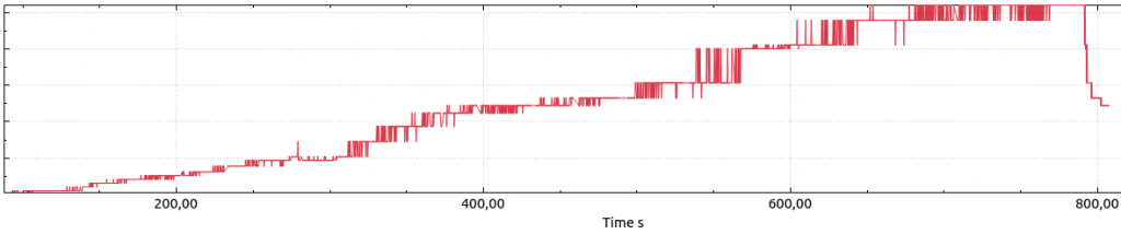
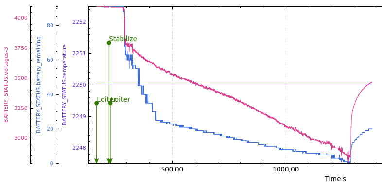
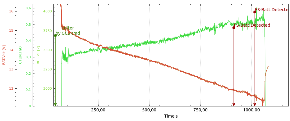
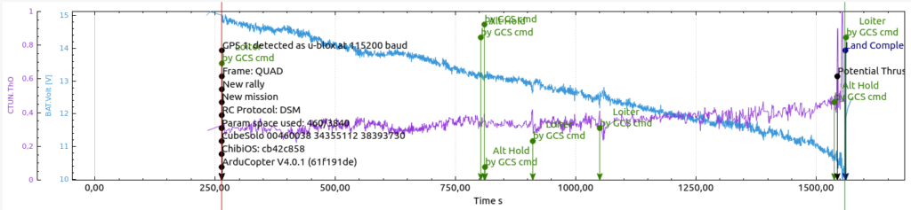
The first graph is made using these packs’ first flight.
It estimates energy as consumed a bit fast in the beginning, then just a little faster after 19/20 minutes.
Then the voltage/capacity table is corrected.. and watch the second graph, beautiful linear estimation, no surprises there even as the battery gets to 2.5v/cell.

Another aspect of SoC by voltage is that it is most accurate when at normal cruise/hover. During a fast climb, the voltage will drop, and while climbing, you will see a lower estimate, and during a fast descend, you will see a higher estimate.
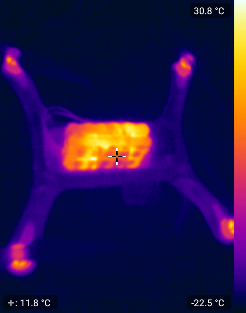
21minute flight example:
(I flew in bad wind conditions, now I see that the flight had the 4.0.3 PID issue that surely affected the flight time in a bad way)
4S3P Samsung INR18650-30Q (12 cells) 620grams with BMSOne.
GoPro Gimbal with Gopro 4 Black. AUW 1950g
Cells bought from Banggood (please observe that this is not a referral link, I get no kickback, nor can I guarantee the authenticity of a later batch).
I landed at 2.6v/cell, yet the manufacturer’s datasheet use 2.5v as the cutoff.
How to make a linearization table:
Let’s say you have a battery with given chemistry that you want to charge to 16.8v max and fly down to 14.0v minimum voltage. None of the known tables work well for it.
On a day with calm or no wind, fly slowly or hover well out of ground effect.
Monitor the voltage of the individual cells and fly the pack down to the desired 0% state, for example, 14v.
The most important part is not to affect the discharge curve by hard flying or rapid climbs/descends. You want to see the pack’s normal voltage drop under normal load.
Get the log from the Solo, and plot BAT. Volt using APMPlanner2 or similar tools.
Now imagine, or draw some number of data points you want to read out, they can be spaced out by time on the x-axis, or better, you can increase density where the voltage is less linear as illustrated with red lines below:
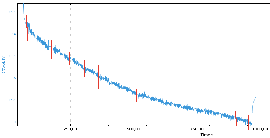
Your first data point would be full pack voltage 16.8v, 100%
The next one, the voltage that is measured right after takeoff, you can see the voltage drop to 16.25v under a given load, but you know it is still full, so the next data point is 16.2v, 99%
The next data point may be read out at the second red line, 15.7v, and the red bar’s position, maybe for example 10% into the flight, – then the remaining capacity(flight time) is 90% – so the next data point is 15.7, 90%
several data points later you land at desired 14.0v … you end up making a final data point 14.0v , 0%.
Now let’s convert the data points to the table: x are points we did not bother to calculate in this example:
SV 14.0, x, x, x, x, x, x, x, x, x, x, x, 15.7, 16.2, 16.8
SP 0, x, x, x, x, x, x, x, x, x, x, x 90, 99, 100
Firmware upgrades:
To flash the new firmware you will need the avrdude application.
On Linux, it’s installed by: “sudo apt install avrdude”
The firmware upload command is:
avrdude -patmega328p -carduino -P /dev/ttyACM0 -b115200 -D -Uflash:w:BMSOne.2.0.hex :i
Windows users may need drivers and the avrdude application: http://download.savannah.gnu.org/releases/avrdude/avrdude-6.3-mingw32.zip and the firmware (download link below). Extract both firmware and avrdude to the same directory.
Then replace the “/dev/ttyACM0” in the example command with the “COMx” name of your serial port, and execute the command.
2.0 Initial release(named 2.0 in order to avoid confusion with BMSOne1.x)
– using 5S/6S spoof 4S for compatibility
2.1: Supports up to 6S – Updated protocol provides all 6 to Ardupilot.
Cell count is auto-detected.
For 3DR Solo, to see 5S/6S : upgraded ArduPilot